Leakage magnetic field detection refers to the formation of a leakage magnetic field on the surface or near surface of a ferromagnetic material due to defects after magnetization.
Leakage magnetic field detection refers to the formation of a leakage magnetic field on the surface or near surface of a ferromagnetic material due to defects after magnetization. People can detect defects by detecting changes in the leakage magnetic field.
Leakage magnetic field refers to the change in magnetic permeability caused by defects or changes in tissue state on the surface of materials that cut magnetic field lines. Due to the small magnetic permeability of defects and the large magnetic resistance, the magnetic flux in the magnetic circuit is distorted, and the direction of magnetic induction lines changes. In addition to some magnetic flux passing directly through the defect or inside the material to bypass the defect, there is also some magnetic flux leaking above the surface of the material, passing through the defect and entering the material again through air, thus forming a leakage magnetic field on the surface of the material.
Magnetic Flux Leakage Testing (MFT) is a very important non-destructive testing method with a wide range of applications. Magnetic particle testing is also a branch of magnetic flux leakage testing. However, the phenomenon of displaying results is identified by the magnetic traces formed by the accumulation of magnetic powder. Magnetic flux leakage testing converts the leakage magnetic field generated by defects into an electrical signal output for inspection personnel to analyze the results. It can be seen that visualizing the intangible magnetic field is a crucial step in magnetic flux leakage testing. Different magnetic measurement principles or components can be used. Usually, the magnetic field is converted into an electrical signal and then automated processing is achieved. In actual testing, there are mainly the following principles and components of magneto electric conversion.
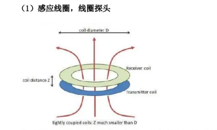
Generate induced voltage by cutting magnetic field lines through coils. The magnitude of induced voltage is linearly related to the number of coil turns, the rate of change of magnetic flux passing through the coil, or the speed at which the coil cuts through magnetic field lines. Induction coils measure the relative changes in magnetic fields and are more sensitive to high-frequency magnetic field signals in the spatial domain. According to different measurement purposes, induction coils can be made in various forms. The number of turns and relative velocity of the coil determine the sensitivity of the measurement, while the geometric shape and size of the coil winding determine the spatial resolution, coverage range, and effective information ratio of the measurement. The premise of using a coil probe is that the field is time varying or the test object is ismoving related
(2) Flux gate
The principle of a flux gate sensor is based on Faraday's law of electromagnetic induction and the nonlinear relationship between the magnetization M and magnetic field H of certain materials. A typical flux gate generally has three windings, namely the excitation winding, the output winding, and the control winding. Magnetic cores are usually track shaped. This type of flux gate has high sensitivity and can measure weak magnetic fields ranging from 10-5 to 107-7T. The output depends on the magnetic characteristics of the magnetic core, and the resolution varies with the size of the magnetic core and coil. In recent years, some scholars have adopted amorphous alloys as the magnetic core of flux gates, which has greatly improved the flexibility of flux gates.

